Mechanics of Materials is 9-14 questions on the FE Mechanical exam. It sits directly between statics, which supplies the internal loads, and mechanical design, which applies them to real components, so it is the hinge of the whole mechanics block.
Most of the difficulty is bookkeeping rather than theory. Sections, axes, units and sign conventions are where the points go, not the constitutive relationships.
Exam weight: NCEES lists Mechanics of Materials at 9-14 questions (8-13%) of the 110-question FE Mechanical exam. Work each problem below on paper first, then reveal the worked solution — reading a solution you have not attempted builds recognition, not recall.
What NCEES Tests in Mechanics of Materials
The specification covers stress and strain including thermal effects, shear and moment diagrams, stress transformation and Mohr's circle, torsion of circular shafts, beam deflection, combined loading, and column buckling. Expect an axial member with a temperature change, a shaft sized for allowable shear stress, and a principal-stress calculation from a plane-stress state.
Combined loading is where mechanical candidates are pushed hardest: a shaft carrying torsion and bending simultaneously, resolved into a principal or maximum shear stress. That single problem type connects to the failure theories in Mechanical Design and Analysis.
5 Free Mechanics of Materials Practice Problems
Each mechanics of materials problem below comes from the PECivilClick FE Mechanical question bank, with worked solutions, and matches the style, difficulty and format of the real exam. Attempt each one under a three-minute limit — roughly the pace the exam demands.
Problem 1 — A. Shear and moment diagrams
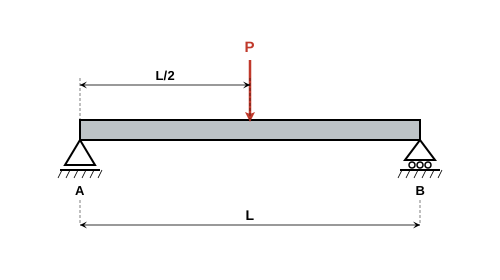
For a simply supported beam with a concentrated load P at the center, what is the maximum bending moment?
Answer: A) PL/4
For a simply supported beam of length L with a concentrated load P at the center:
Reactions: \(R_A = R_B = P/2\)
Maximum moment occurs at the center:
\(M_{max} = R_A \times \frac{L}{2} = \frac{P}{2} \times \frac{L}{2}\)
\(\boxed{M_{max} = \frac{PL}{4}}\)

Problem 2 — A. Shear and moment diagrams
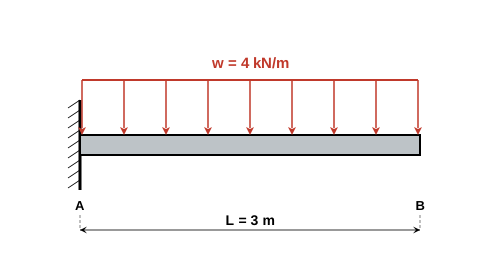
A cantilever beam of length 3 m carries a uniformly distributed load of 4 kN/m. What is the maximum bending moment?
Answer: C) 18 kN·m
For a cantilever with UDL \(w\) over length \(L\):
Maximum moment occurs at the fixed end:
\(M_{max} = \frac{wL^2}{2}\)
\(M_{max} = \frac{4 \times 3^2}{2} = \frac{36}{2}\)
\(\boxed{M_{max} = 18 \text{ kN·m}}\)
The moment is negative (causing hogging at the fixed end).

Problem 3 — A. Shear and moment diagrams
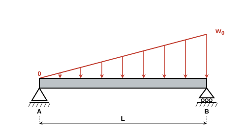
At what location does the maximum bending moment occur in a simply supported beam with a triangular load (zero at left, w\(_{0}\) at right)?
Answer: D) At L/\(\sqrt{3}\) from the left support
For triangular load \(w(x) = w_0 x/L\), total load \(= w_0 L/2\), acting at \(2L/3\) from left.
Left reaction: \(R_A = \frac{w_0 L}{6}\)
Shear at distance \(x\) from left:
\(V(x) = R_A - \frac{w_0 x^2}{2L} = \frac{w_0 L}{6} - \frac{w_0 x^2}{2L}\)
Maximum moment occurs where \(V = 0\):
\(\frac{w_0 L}{6} = \frac{w_0 x^2}{2L}\)
\(x^2 = \frac{L^2}{3}\)
\(\boxed{x = \frac{L}{\sqrt{3}} \approx 0.577L}\)

Problem 4 — A. Shear and moment diagrams
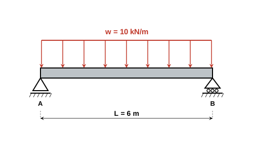
A simply supported beam of length 6 m carries a UDL of 10 kN/m. What is the maximum shear force?
Answer: B) 30 kN
Total load: \(W = wL = 10 \times 6 = 60\) kN
By symmetry, reactions: \(R_A = R_B = W/2 = 30\) kN
Maximum shear occurs at the supports:
\(\boxed{V_{max} = 30 \text{ kN}}\)
The shear diagram is linear, going from +30 kN at left support to -30 kN at right support, passing through zero at midspan.

Problem 5 — B. Stress transformations and Mohr's circle
The center of Mohr's circle is located at:
Answer: D) (σx + σy)/2 on the σ-axis
For Mohr's circle construction:
\(\boxed{\text{Center: } C = \frac{\sigma_x + \sigma_y}{2}}\)
on the normal stress axis.
\(\text{Radius: } R = \sqrt{\left(\frac{\sigma_x - \sigma_y}{2}\right)^2 + \tau_{xy}^2}\)
The center represents the average normal stress, and the radius represents the maximum shear stress.
Using the FE Reference Handbook for Mechanics of Materials
Everything here is tabulated: section properties, beam deflection cases, torsion formulas and the Euler buckling relationship. The trap is the beam deflection table, which is organised by load and support case, so you must read the diagram at the top of each entry rather than matching on the formula shape. Practise finding the simply-supported-with-central-point-load case and the cantilever-with-end-load case by sight.
Four Mistakes That Cost Points
- Using the wrong second moment of area. Bending about the strong axis uses I about that axis; buckling uses the smallest I of the section unless bracing prevents that mode. Reading the wrong column of a section table gives an answer that is present among the options.
- Mixing radius and diameter in torsion. The polar moment for a solid circular shaft goes as diameter to the fourth over thirty-two, or radius to the fourth over two. Substituting a diameter where a radius belongs is a factor of sixteen, and it is the most common error in torsion problems.
- Restraining a thermally loaded member incorrectly. A bar free to expand develops strain but no stress. A fully restrained bar develops stress but no net strain. Deciding which case applies is the whole problem, and both answers appear.
- Reading Mohr's circle at the wrong angle. Angles on Mohr's circle are twice the physical angle. Rotating the element by thirty degrees means rotating sixty degrees on the circle, and forgetting the factor of two is a designed distractor.
Frequently Asked Questions
How many mechanics of materials questions are on the FE Mechanical exam?
NCEES specifies 9-14 questions out of 110, roughly 8-13 percent. Combined with Statics at 9-14 and Mechanical Design and Analysis at 10-15, the solid mechanics block is the largest part of the exam.
Do I need to draw shear and moment diagrams by hand?
Often you only need one value, not the whole diagram. Read the question first: if it asks for maximum moment on a standard load case, the handbook beam tables give it directly. Draw the diagram when the loading is non-standard or when the question asks where the maximum occurs.
How much does Mohr's circle actually appear?
Stress transformation is a reliable part of this area, and it can be done with the handbook equations rather than by drawing the circle. Knowing both routes helps: the equations are faster for a single principal stress, the sketch is faster for reasoning about orientation.
Is column buckling tested on FE Mechanical?
Yes, as Euler buckling with an effective length factor. Know the four standard end conditions and their factors, and remember that buckling uses the minimum second moment of area of the cross-section.
Keep Going
These topics feed into each other on the exam:
- FE Mechanical Statics practice problems — 9-14 questions on the exam
- FE Mechanical Mechanical Design and Analysis practice problems — 10-15 questions on the exam
- FE Mechanical Material Properties and Processing practice problems — 7-11 questions on the exam
Done with mechanics of materials? Browse every knowledge area from the free FE Mechanical practice problem hub, see what the full bank covers on the FE Mechanical exam prep page, or plan your schedule with the FE study timeline.